


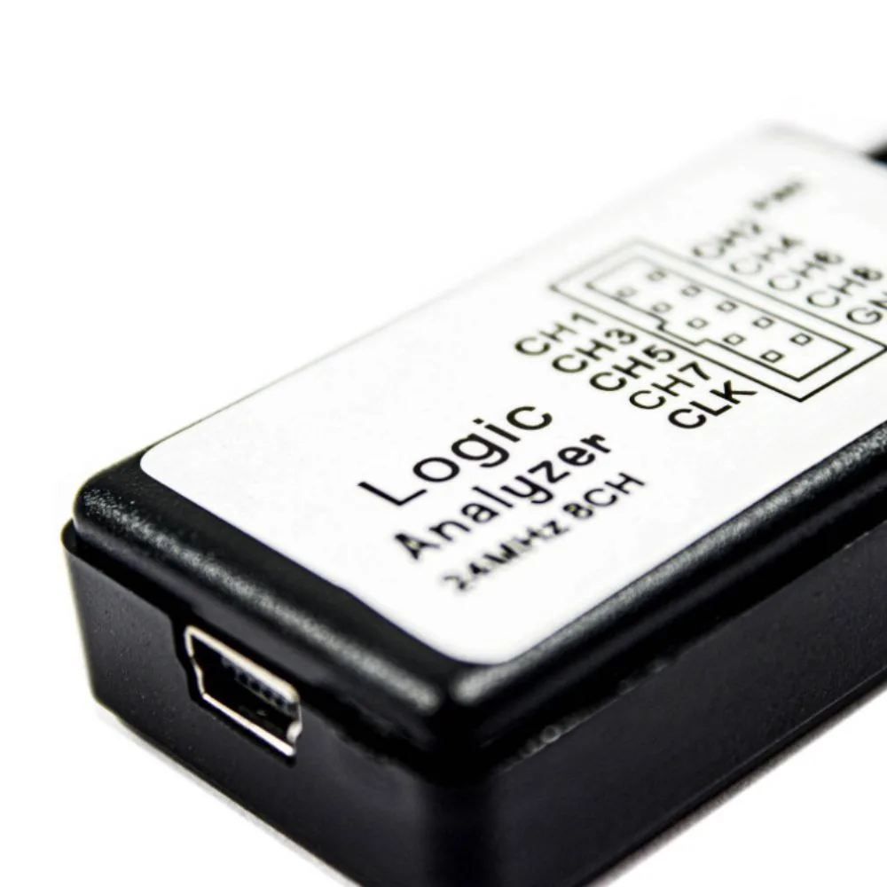
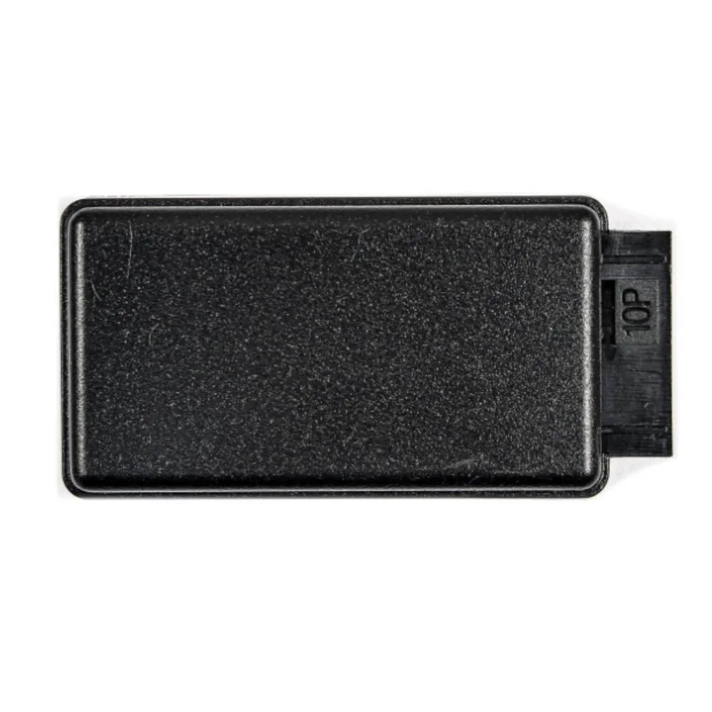
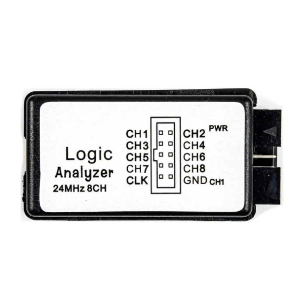
The 24 MHz 8-Channel USB Logic Analyzer is a compact electronic debugging tool used to capture and analyze digital signals from circuits such as microcontrollers, embedded systems, and communication buses. It connects to a computer through USB and displays digital waveforms using specialized analysis software.
This device is widely used for Arduino, ESP32, ARM, FPGA, and IoT development, allowing engineers and students to monitor signals like UART, SPI, and I²C communication.
Features
-
8 digital input channels
-
Maximum sampling rate: 24 MHz
-
USB powered (no external power needed)
-
Includes test probes / Dupont wires
-
Compatible with Windows, Linux, macOS
-
Supports protocol decoding (UART, SPI, I²C, CAN)
-
Adjustable sampling rates from 25 kHz to 24 MHz
Specifications
| Parameter | Specification |
|---|---|
| Channels | 8 digital channels |
| Maximum Sampling Rate | 24 MHz |
| Input Voltage Range | −0.5 V to 5.25 V |
| Logic Levels | Compatible with 5 V and 3.3 V systems |
| Input Impedance | ~1 MΩ / 10 pF |
| Power Supply | USB |
| Interface | USB to PC |
| Size | ~54 × 27 × 15 mm |
| Supported Software | PulseView / Sigrok / Saleae-compatible |
The sampling rate can be configured to 24 MHz, 16 MHz, 12 MHz, 8 MHz, 4 MHz, 2 MHz, and lower, depending on the measurement requirements.
Supported Protocol Analysis
This logic analyzer can decode common digital communication protocols:
-
UART / Serial
-
SPI
-
I²C
-
CAN
-
1-Wire
This helps developers debug communication between microcontrollers and peripherals.
Applications
Typical uses include:
-
Microcontroller debugging (Arduino, ESP32, STM32)
-
Communication protocol analysis
-
Embedded system development
-
Electronics education and labs
-
Hardware troubleshooting
-
Reverse engineering digital circuits
Basic Connection Example
————– —————-
CH0 ————– TX
CH1 ————– RX
CH2 ————– SCK
CH3 ————– MOSI
CH4 ————– MISO
GND ————– GND
Then the signals appear as digital timing diagrams in the PC software.
Advantages
Very low cost debugging tool
Portable and easy to use
Supports multiple communication protocols
Works with open-source analysis software


There are no reviews yet.