


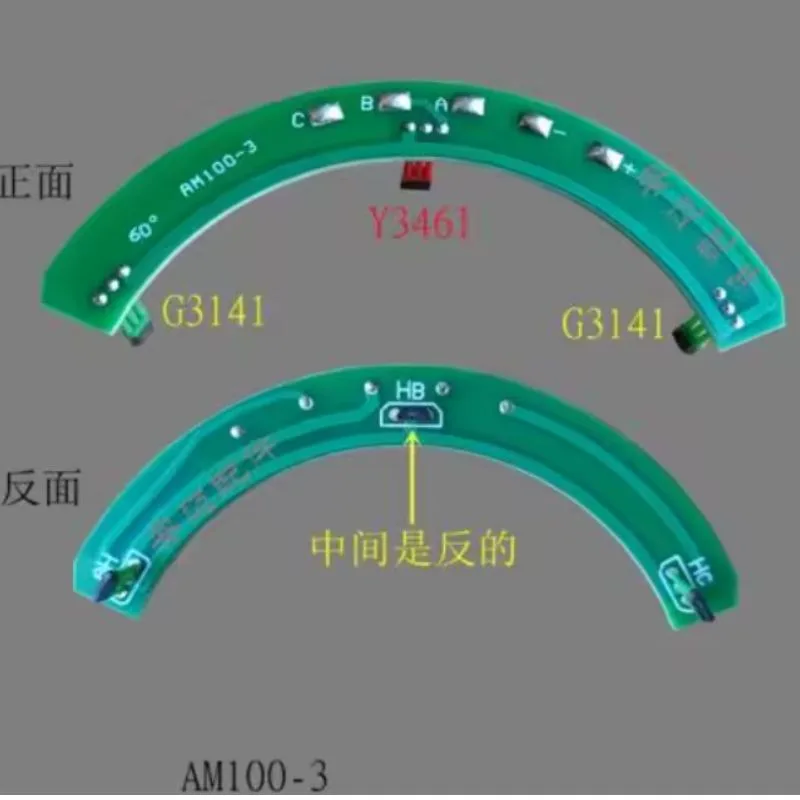


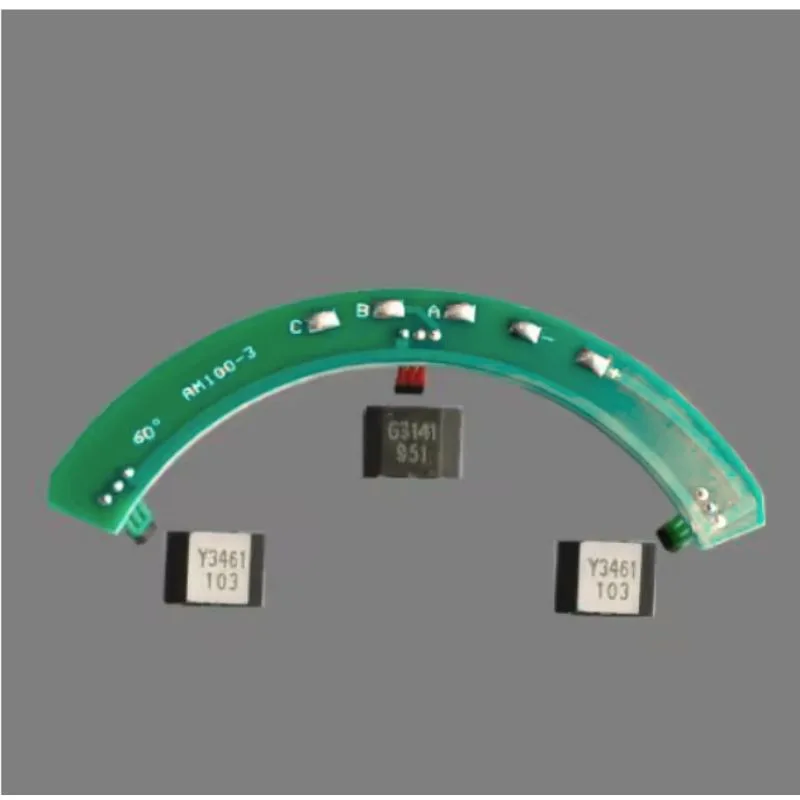
Hall elements” / “Hall sensor PCB” for EV hub motors are small PCBs that contain 3 (or sometimes 5) Hall sensors plus the cable/connector used by motor controllers to detect rotor position. They’re commonly used in brushless DC (BLDC) hub motors for 2/3/4-wheel scooters, tricycles, and small electric vehicles. Supplier listings often label commonly-used replacements with codes like Y3461, G3141, Y3141, 461, 3141 — these are vendor part IDs rather than a single manufacturer IC.
Typical features & functional role
-
Function: provide 3 rotor-position signals (Hall pulses) timed ~120° electrical apart for closed-loop commutation or to generate reference for sine-wave control. The controller uses them to switch phases (or to calibrate FOC) so the motor produces smooth torque.
-
Form factor: small circular/rectangular PCB that mounts inside the motor near the stator/air gap, often with a short cable and 6–7-pin connector (3 Hall outputs + 3 phase sense or Vcc/GND + optional temp/led). Many replacement listings are “Hall PCB with cable” for 1,000–2,000 W hub motors.
-
Sensor ICs used: boards often use general Hall ICs (examples: Allegro/Alldatasheet families like the 3141 series or generic switches) or SS460/SS49 style sensors depending on board design. Datasheets for common Hall ICs are used for reference by sellers.
Representative electrical specifications (typical values)
(Exact numbers vary by vendor — treat these as typical ranges.)
-
Supply voltage (Vcc): usually 4.5–24 V tolerated on many boards, but commonly powered from 5–12 V from controller’s Vcc/Hall supply. Confirm your controller’s hall-supply voltage.
-
Outputs: open-collector or push-pull Hall outputs, TTL/logic level pulses. Expect 3 outputs labelled H1/H2/H3.
-
Temperature range & robustness: automotive/two-wheel replacements are designed for elevated temps (often –40 to +85 °C or more). Check listing for exact rating.
-
Compatibility: labeled for “sine wave 1000–2000W / 1500W motors” in many online listings — they’re marketed as replacements for common 120° Hall motors. Always verify pole-pair count and cable pinout.
Wiring & connector (how these boards integrate)
Typical wires on the hall-PCB cable (but confirm pinout on the specific product — vendors differ):
-
VCC (Hall +5V or +12V) — usually red
-
GND — usually black
-
HALL A / HALL B / HALL C — three signal wires (often in sequence)
-
Optional: temp sensor, rotor speed output, or LED
Controllers expect the 3 Hall signals to be spaced 120° electrical; if miswired you get noisy commutation or wrong rotation direction (swap any two Hall wires to invert rotation). Many replacement listings show the AM100-3 / 461 type boards with standard 6/7-pin connectors.
Using with a 1500 W sine-wave motor / controller
-
Sine-wave controllers & Hall sensors: modern sine-wave (or FOC) controllers may use Hall sensors for initial rotor alignment and low-speed commutation, then rely on back-EMF or encoder feedback at higher speed. A correct Hall board will let a sine-wave controller commutate smoothly at low speeds and start reliably. Many vendors sell boards explicitly marketed for 1,000–2,000 W sine-wave hub motors.
-
Check pole-pairs / electrical angle: ensure your motor is 120° Hall-phased (most standard BLDC hub motors are) — if your motor’s Hall angle differs, the controller may require configuration or different board. Sellers usually state “for 4601 sine wave motor / 1500W” if compatible.
Installation & replacement checklist
-
Confirm pinout on old cable and new board (visually map Vcc/GND/H1/H2/H3). Don’t assume colors. Mounting: fit the PCB into the original slot / screw holes so sensors sit in the designed gap to the rotor magnets. Incorrect air-gap affects timing/strength.
-
Use same cable length / strain relief — avoid pulling or sharp bends that stress solder joints.
-
Verify supply voltage to the Hall board matches the controller’s Hall supply (5V vs 12V). Some boards accept both, but confirm.
-
Test before reassembling motor fully: with motor open, power the hall supply and spin rotor by hand (or slowly power motor) and use a scope / multimeter to watch pulses on the three Hall lines (should be three clean pulses per electrical revolution spaced equally). YouTube tutorials show this test procedure.
Troubleshooting common issues
-
No start / jitter at low speed: check Hall wiring order & Vcc/GND; swap any two Hall signals to reverse rotation if direction wrong.
-
Noise / missed commutation: dirty/damaged board, magnets too far or misaligned, or incorrect air-gap. Clean & remount.
-
Hall pulses present but controller faults: check levels with oscilloscope; ensure pull-up/pull-down expectations match controller (open-collector vs push-pull).
-
Intermittent faults: often cable/connector damage or cold solder joints on the tiny board; replacement boards are inexpensive on marketplaces.
Buying & compatibility tips
-
Buy the same physical board type (pinout and mounting) when possible — many sellers list OEM replacement numbers (Y3461 / G3141 / 461 / 3141 etc). Listings on Alibaba/Lazada/eBay show many compatible boards marketed for 3-wheel/4-wheel hub motors.
-
Ask the seller for a pinout diagram and confirm the supported Hall supply voltage and intended motor wattage (your 1,500 W rating).
-
Consider buying a small spare — they’re cheap and replacing the board is often faster than diagnosing intermittent issues. Typical price in online shops ranges low (single-digit USD to teens).
Alternative / compatible Hall ICs & parts
-
If you need replacement IC rather than full PCBs, common Hall IC families (Allegro 314x / A314x / SS460 variants) are used in many designs as the sensing element — check the board marking to identify the exact IC. Use the IC datasheets for electrical limits.
Safety & final tips
-
Disconnect battery before working inside the hub motor.
-
Mark cable orientation before removing old board so rewire is easier.
-
Use an oscilloscope if available to ensure Hall timing and amplitude are correct before re-assembly.
-
Buy from sellers with good photos & pinout info — many marketplace listings are generic images; confirm it physically matches your old board


There are no reviews yet.