


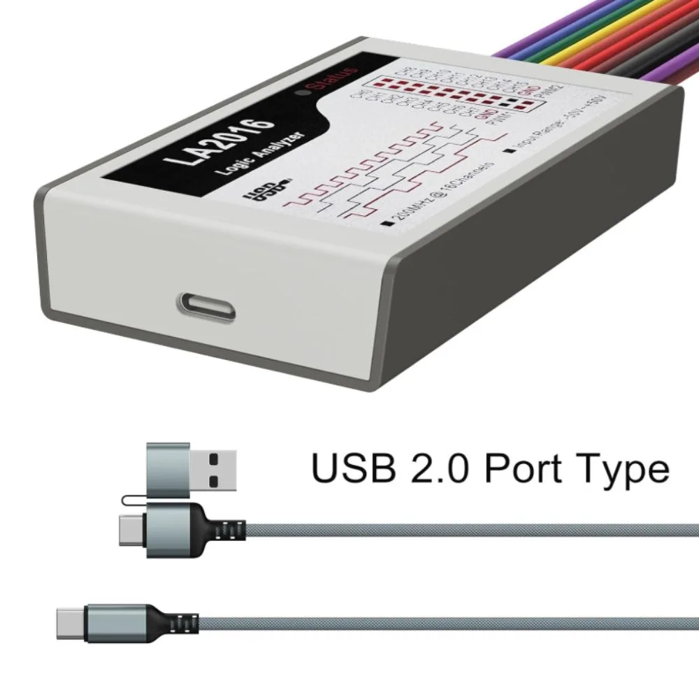

The InnoMaker LA2016 USB Logic Analyzer is a professional digital debugging tool used to capture and analyze digital signals from electronic circuits. It provides 16 input channels and a maximum sampling rate of 200 MHz, allowing engineers, students, and developers to observe communication signals in real time.
This device connects to a computer via USB and works with powerful PC analysis software that supports Windows (32-bit/64-bit), macOS, and Linux. It is widely used for debugging microcontrollers, embedded systems, communication protocols, and digital electronics.
Features
-
16 digital input channels for multi-signal analysis
-
Maximum 200 MHz sampling rate for high-speed signal capture
-
Works with Windows, macOS, and Linux systems
-
USB interface for easy connection to PC
-
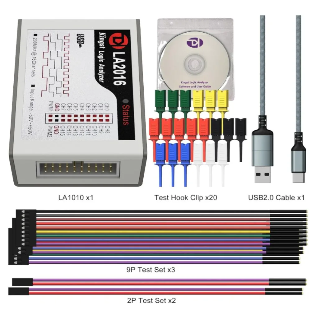
Includes probe cables and clips for quick testing
-
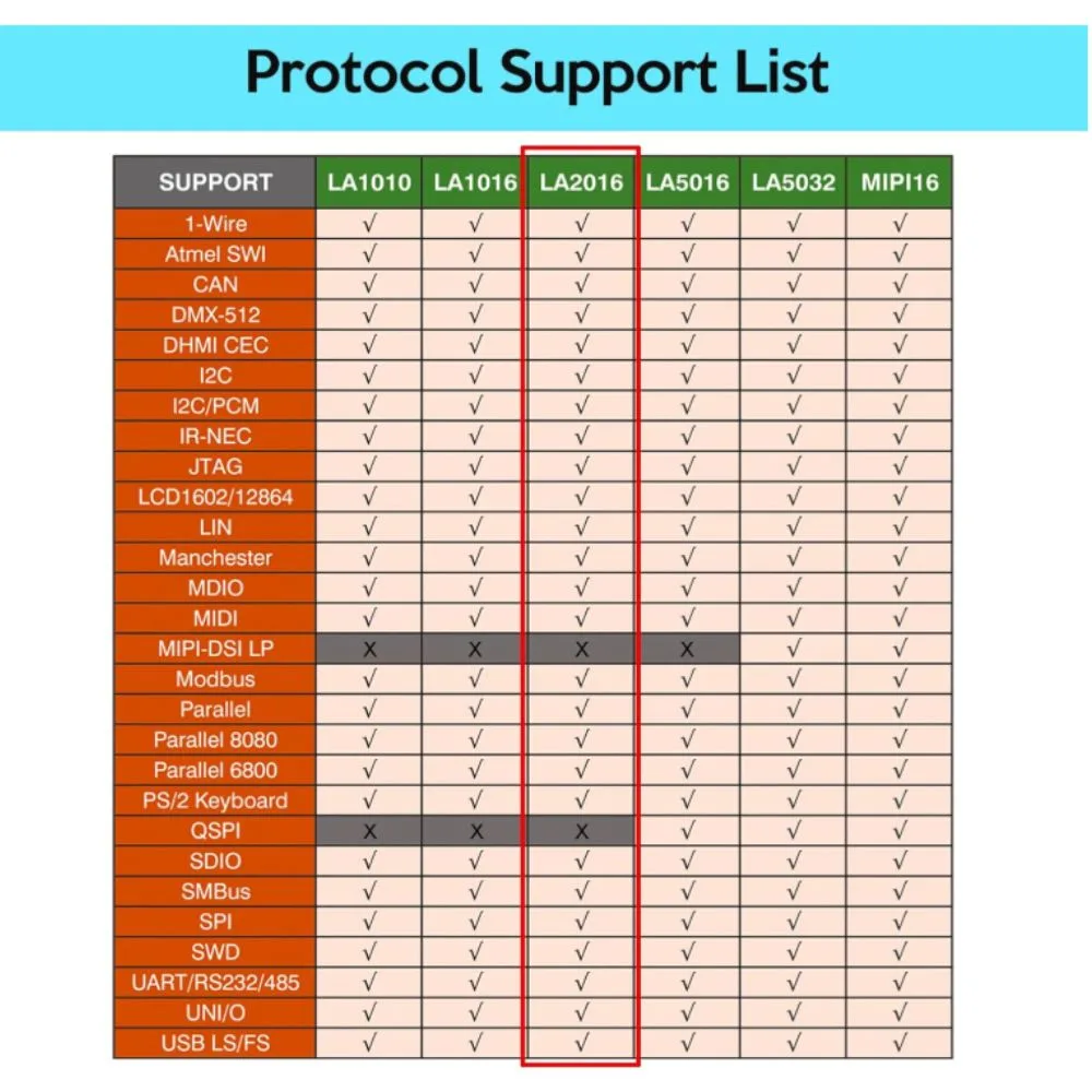
Supports decoding of many communication protocols
-
Real-time waveform display and signal analysis
-
Compact and portable handheld design
Specifications
| Parameter | Specification |
|---|---|
| Model | LA2016 |
| Number of Channels | 16 |
| Maximum Sampling Rate | 200 MHz |
| Input Voltage | 0 V – 5 V logic level |
| Interface | USB |
| Trigger Modes | Edge, pulse, and pattern trigger |
| Supported Systems | Windows (32/64-bit), macOS, Linux |
| Software | PC logic analyzer software |
| Dimensions | Compact handheld device |
| Applications | Digital signal analysis and debugging |
Main Parts of the Logic Analyzer
1. USB Interface
Used to connect the analyzer to a computer for data transfer and power.
2. 16-Channel Input Port
Allows connection of up to 16 digital signals simultaneously.
3. Probe Cables and Clips
Used to connect the analyzer to microcontroller pins, buses, or digital circuits.
4. PC Analysis Software
Displays timing diagrams, waveforms, and protocol decoding results.
Supported Protocol Analysis
The LA2016 logic analyzer can decode many digital communication protocols such as:
-
UART / Serial
-
SPI
-
I²C
-
CAN
-
1-Wire
-
I²S
-
Parallel bus signals
This makes it useful for embedded development and hardware debugging.
Applications
The LA2016 USB Logic Analyzer is commonly used in:
-
Microcontroller debugging (Arduino, ESP32, STM32)
-
Embedded system development
-
Communication protocol analysis
-
Digital electronics laboratories
-
Engineering education and research
-
Hardware troubleshooting
Basic Usage Steps
-
Install the logic analyzer software on your PC.
-
Connect the LA2016 device via USB.
-
Attach probe clips to the digital signal pins.
-
Select sampling rate and trigger settings.
-
Start capture and analyze the waveform data.
Usage Tips
Use proper grounding when connecting probes
Choose the correct sampling rate for accurate capture
Avoid signals exceeding the maximum voltage rating
Label channels in the software for easier analysis
Maintenance
-
Store the analyzer in a dry, dust-free environment
-
Avoid pulling or bending probe cables excessively
-
Disconnect probes after use
-
Keep USB port clean to ensure stable connection


There are no reviews yet.