


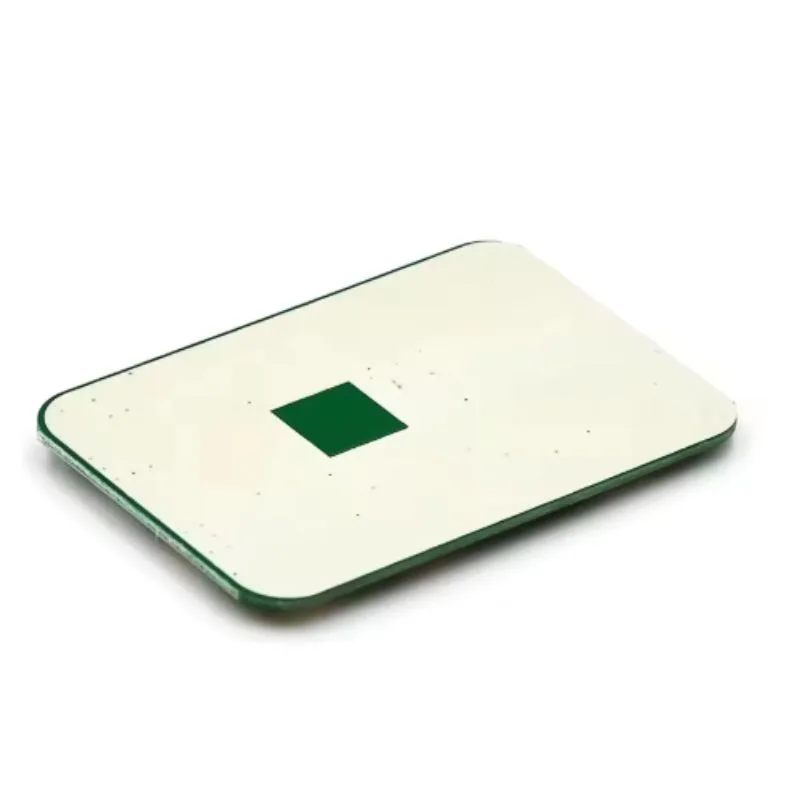
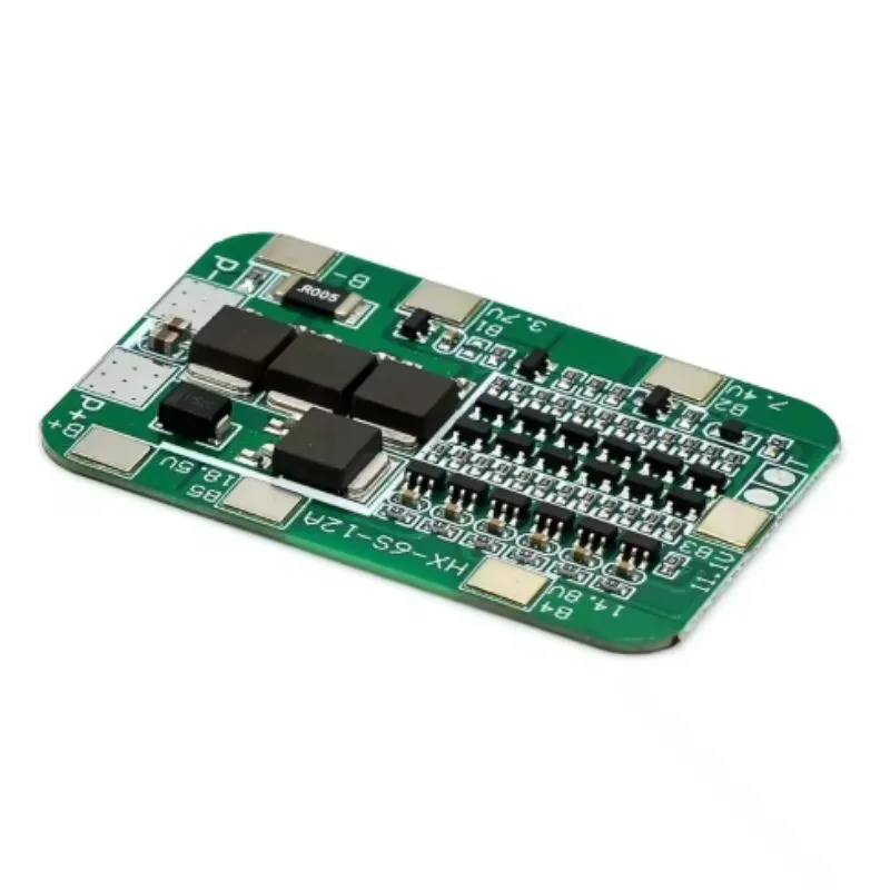
A Battery Management System (BMS) or Protection Circuit Module (PCM) is an electronic module installed in multi-cell lithium battery packs (e.g. Li-ion, Li-polymer, LiFePO₄, etc.) to monitor and protect cells from operating outside safe limits. The “6S 22.2 V 10 A LWS” version is designed for a pack of 6 lithium cells in series (nominal ~22.2 V) and supports a continuous current of around 10 A (charge/discharge) while providing various protections (overcharge, overdischarge, overcurrent, short circuit, balancing, etc.).
The “LWS” is a brand or model designation (often from Chinese manufacturers) for this BMS/PCM module. For example, a listing describes “LWS 6S 22.2V 10A Battery BMS / PCM” with balance and full protection features.
This kind of BMS is used in battery packs for e-bikes, electric scooters, portable power systems, DIY battery packs, and other energy storage solutions where you need to prevent overcharging, overdischarging, cell imbalance, current surges, and short circuits.
Features
Here are the typical features you’d expect from this LWS 6S 22.2 V 10 A BMS / PCM:
-
Cell count support: 6 cells in series (6S)
-
Nominal voltage: ~22.2 V (6 × ~3.7 V nominal)
-
Maximum continuous charge / discharge current: ~10 A
-
Protection features:
-
Overcharge protection (cut off charging when cell voltage too high)
-
Overdischarge protection (cut off discharging when cell voltage too low)
-
Overcurrent / overload protection (when load current is too high)
-
Short-circuit protection
-
Cell balancing — ensures that all cells in the series string remain close in voltage during charging
-
Possibly temperature protection (some BMS modules include a thermistor / temperature sensor input)
-
-
Balance current: A modest balancing current per cell (for equalizing voltage during charging) — often tens of milliamps. For example, a listing gives “balance current for single cell 42 mA” for a similar BMS.
-
Voltage thresholds:
-
Overcharge detection voltage per cell: around 4.28 V ± tolerance
-
Overcharge release voltage: ~4.05 V ± tolerance
-
Overdischarge detection voltage per cell: ~3.00 V ± tolerance
-
Overdischarge release: ~3.00 V ± tolerance
-
-
Operating temperature range: e.g. –20 °C to +70 °C
-
Physical / mechanical:
-
Board dimensions: e.g. 108 × 35 × 4 mm (according to one listing)
-
PCB copper thickness, traces, layout to handle currents
-
Connection pads or pins for series cell taps (B–, B1, B2, …, B6), pack positive/negative, etc.
-
-
Low quiescent current / standby consumption: so that the BMS itself does not drain the battery significantly when idle
-
MOSFET or switch units: typically high-current MOSFETs used for switching off load/charge paths
Some listings also mention the ability to use for LiFePO₄ by altering certain settings or component choices.
Tips / Best Practices for Using This BMS
When implementing or using this LWS 6S 22.2 V 10 A BMS, follow these best practices and cautions:
-
-
Ensure correct wiring of all cell taps
The BMS needs to “see” each series cell voltage via its balance taps (B–, B1, B2… up to B6). If any tap is miswired or disconnected, the BMS can malfunction or misinterpret voltages. -
Match BMS current specs to your load / battery
Just because the BMS is rated for 10 A doesn’t mean you should continuously pull 10 A — leave headroom. If your application draws spikes or continuous loads near 10 A, ensure cooling and verify temperature behavior. -
Provide good thermal / heat management
MOSFETs, sense resistors, and balancing circuits can generate heat under load. Use proper heat dissipation (heat sinks, ventilation) if placed inside enclosures. -
Use a fuse or external protection
Even though the BMS has overcurrent protection and short-circuit protection, it’s wise to include a fuse or circuit breaker on the pack’s positive output to add a layer of safety. -
Balance during charging
The balancing function works best when the pack is near full charge. Avoid deep balancing under heavy loads; ensure cells are as equal as possible before charging. -
Avoid discharging below safe voltage
The BMS will cut off the load if a cell drops below safe thresholds, but it’s better to avoid pushing the battery to extremes. Monitor cell voltages. -
Avoid high currents at low voltage
Near depletion, cells have higher internal resistance; drawing high current when the pack is low can cause voltage sag, triggering the BMS cutoff or harming cells. -
Check BMS quiescent / standby current
The BMS itself draws a small current even when idle. In battery packs with low leak or standby loads, this matters over long durations. -
Ensure good PCB layout and wiring
Use thick wires, short traces, and proper soldering for the high-current paths to minimize voltage drops and heating. -
Test under different conditions
Before deploying in a final product, test with varying loads, ambient temperatures, and charge/discharge cycles to ensure the BMS behaves consistently. -
Respect temperature limits
If the BMS includes temperature protection or sensor input, make sure the sensor is placed on or near the hottest component (usually MOSFETs) and that ambient conditions don’t exceed rated range. -
Check for firmware / tolerance differences
Some BMS boards have variants or revisions. If possible, get the datasheet or test each unit to confirm thresholds (overcharge, overdischarge, balancing behavior). -
Insulate and protect in enclosure
Ensure that the BMS board is properly insulated and protected from shorts, moisture, vibration, or mechanical stress inside the battery pack. -
Document pinouts and labels
Mark which pin is which (B–, P–, P+, B1, B2, …) clearly so you or others don’t misconnect in future.
-


There are no reviews yet.