

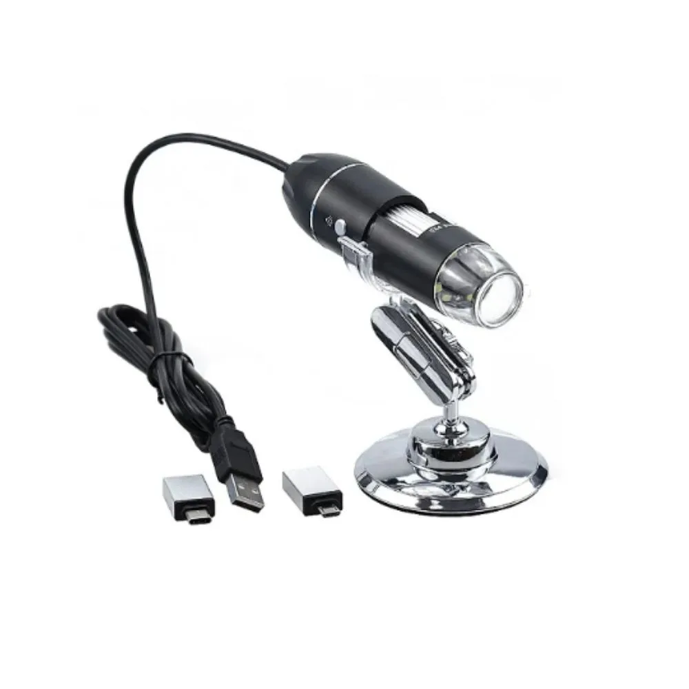


A USB digital microscope is essentially a camera with a macro / high-magnification lens assembly, built-in lighting (LEDs), and a USB interface for live video / image capture. The “Type-C” designation means it can be directly plugged into devices that have a USB-C port (smartphones, tablets, newer computers) (often via an OTG adapter or inbuilt support).
For electronics work (soldering, inspection), these digital microscopes allow you to see fine traces, solder joints, component leads, etc., magnified on a screen (phone, PC) — easier to inspect and work precisely.
Many models claim up to 1000× magnification (though “1000×” is often a marketing exaggeration; realistic usable magnification is less, depending on optics, sensor, lighting, etc.). You’ll find features like adjustable focus, LED ring lighting, stand / holder, image capture, measurement software, etc.
USB microscopes are commonly described in this way: “essentially a webcam with a high-powered macro lens” with built-in illumination.
Key Features
Here are the features you should look for or expect in a high-quality Type-C USB digital microscope:
| Feature | Description / Importance |
|---|---|
| Interface / Connectivity | USB-C or USB (with adapter) for plug & play with PCs / Android / OTG devices |
| Sensor / resolution | CMOS sensor with resolution adequate for capturing detail (e.g. VGA, HD, 2MP, etc.) |
| Frame rate | 30 fps is common for smooth video |
| Magnification / zoom | Claimed up to 1000× (optical + digital) — realistic effective magnification will be lower |
| Focusing / working distance | Adjustable focus (manual) and a useful working distance (distance from lens to object) |
| Lighting / LEDs | Built-in LEDs (often ring or around lens) to illuminate the object; adjustable brightness is helpful |
| Stand / holder | Many come with a stand or bracket (adjustable height) to keep stable during use |
| Image capture / video | Ability to capture still images (JPG/BMP) and record video (AVI, etc.) via software |
| Measurement / calibration | Some software allows measuring distances in the image (micron/mm scale) |
| Compatibility | Works with Windows, macOS, Linux, Android (via OTG) — check driver / app support |
| Durability / build | Good lens, stable mechanical parts, solid housing |
| Power / consumption | Powered via USB (5 V from host); low current usage |
| Lighting control | Ability to dim or turn off LEDs; pattern lighting (some models use multiple LEDs or ring lights) |
For example, a “1000X USB Digital Microscope with 8 LED Lights – Type-C and Android/PC Compatible” is one such product.
Another “3 in 1 Port Type-C 1000×” digital microscope is described with a 1.3 M CMOS sensor, manual focus, 8 built-in LEDs, and frame rate up to 30 fps.
Typical Specifications (Example)
Below is a representative spec sheet based on typical models and listings like those above:
| Parameter | Typical / Claimed Value |
|---|---|
| Sensor | CMOS (often 1.3 MP, VGA, or similar) |
| Maximum Image Resolution | e.g. 640 × 480, or up to 1920 × 1440 in some models |
| Frame Rate | 30 fps |
| Interface | USB Type-C (or Adapter for Type-C) |
| Magnification | Up to 1000× (optical + digital) |
| Focusing Range / Working Distance | ~ 15 mm to 40 mm (varies) |
| LED Lighting | 8 built-in white LEDs, adjustable brightness |
| Power Supply | 5V DC via USB |
| Operating Systems | Windows, Mac OS, Linux, Android (OTG) |
| Body / Housing | Plastic / ABS or metal in higher-end variants |
| Stand / Bracket | Adjustable stand often included |
| Video Format | Usually AVI or standard formats; snapshot JPG / BMP |
| Software | Included software / drivers for capture, measurement, etc. |
Note: Many models use digital zoom in addition to optical magnification; the advertised “1000×” might rely heavily on digital magnification, which can degrade image quality.
Tips for Using a USB Digital Microscope for Soldering / Repairs
Here are best practices to get the most out of your digital microscope:
-
Use a stable stand / mount
Vibration or hand movement will distort your view — a stand or articulated arm helps maintain focus. -
Proper lighting control
Adjust LED brightness so you have enough illumination without glare or reflection on shiny surfaces. -
Calibrate measurement functions
If your software supports measurement, calibrate using a known scale (e.g. a calibration slide or ruler) before measuring component dimensions. -
Keep working distance in mind
Don’t press the lens too close to the PCB; maintain the focus range for best resolution. -
Reduce ambient light interference
Use shading or cover to reduce stray light, reflections, or shadows. -
Clean optics and sample
Dust, flux residue, fingerprints degrade image clarity — keep lens and sample clean. -
Use software features
Many capture software supports freezing, stacking, partial magnification, brightness / contrast adjustments; learn those features. -
Beware of heat / solder fumes
Prolonged exposure to soldering heat, fumes or smoke may degrade the lens or fog; ventilate well. -
Use proper USB / power source
Ensure your host (phone, PC) supplies stable 5 V and enough current; some phones may need OTG support or adapters. -
Lens alignment
Center the object under the lens or move sample rather than lens for best control. -
Avoid over-reliance on digital zoom
Digital zoom usually degrades image quality; optical focus & quality matter more. -
Work in monochrome / high contrast when needed
For inspecting traces or cracks, sometimes switching to monochrome / high contrast settings helps. -
Take snapshots / video for record
Useful to compare before/after repair, document faults. -
Practice focusing and movement
Familiarize with minuscule movements — moving the sample slightly can reposition features under view.


There are no reviews yet.