

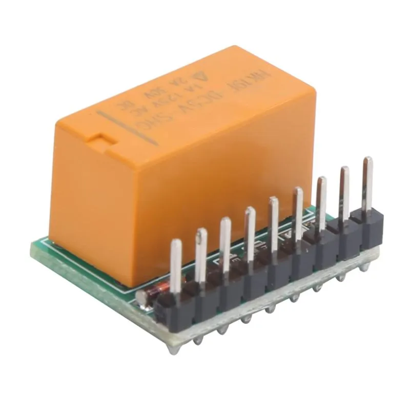
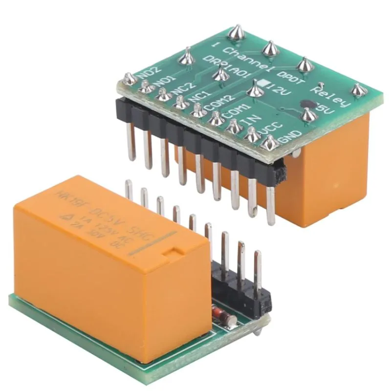
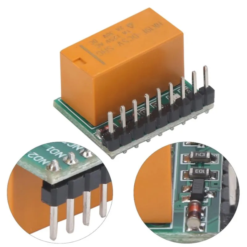
The Ultra-small DPDT 5V Relay Module is a miniature polarity reversal switch designed to change the direction of current flow in a DC load, most often a DC motor.
It integrates:
-
A DPDT (Double Pole Double Throw) relay
-
Driver transistor and flyback diode
-
Indicator LED
-
Control input pin (5V logic)
This module allows you to reverse motor direction (forward/reverse) using a single control signal, acting as a compact H-Bridge alternative.
Key Features
| Feature | Description |
|---|---|
| Operating Voltage | 5 V DC |
| Control Logic | Active HIGH (5V = ON, 0V = OFF) |
| Relay Type | DPDT (Double Pole Double Throw) |
| Contact Form | 2 Form C (changeover contacts) |
| Max Load Current | 2A – 5A (depending on relay rating) |
| Max Switching Voltage | 30 VDC or 250 VAC |
| Channel Count | 1 |
| Relay Isolation | Electromagnetic (mechanical contact) |
| Indicator LED | Shows ON/OFF state of the relay |
| Size | Ultra-compact (typically 25 × 15 × 18 mm) |
| Driver Circuit | Transistor + Flyback diode built-in |
| Mounting Type | 4-pin header / screw terminals (varies) |
Working Principle
The module’s DPDT relay switches both the positive and negative terminals of the load when activated.
That effectively reverses the polarity to the motor or device connected, reversing its direction.
| Relay State | Connection | Motor Direction |
|---|---|---|
| OFF | COM → NC | Forward |
| ON | COM → NO | Reverse |
This is equivalent to cross-wiring the polarity of a DC motor.
Pin Configuration
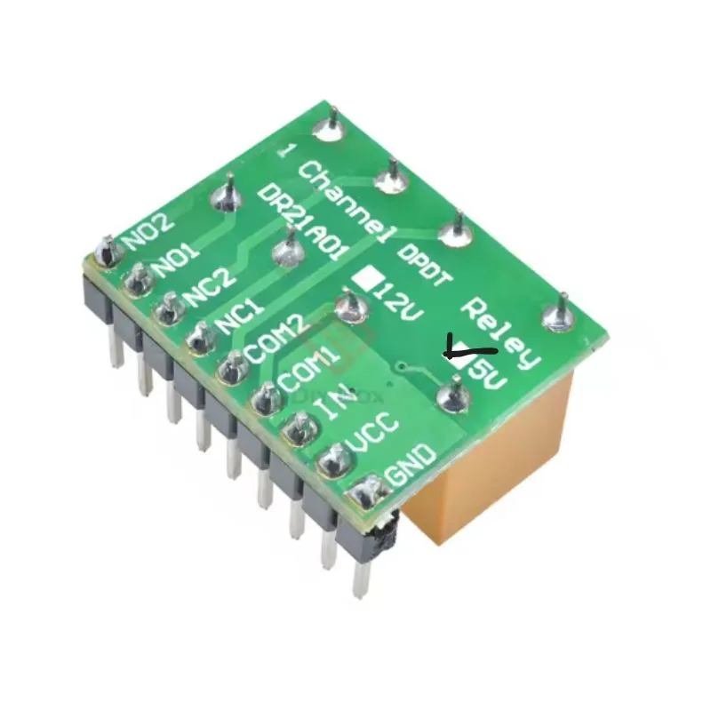
| Pin | Label | Description |
|---|---|---|
| 1 | VCC | +5 V power input (relay & driver circuit) |
| 2 | GND | Ground |
| 3 | IN | Signal input (HIGH = relay ON, LOW = relay OFF) |
| 4 | NC | Normally Closed connection (motor terminal side) |
| 5 | COM | Common output (to motor) |
| 6 | NO | Normally Open connection (motor terminal side) |
Some modules have dual output terminals (COM1/COM2, NO1/NO2, NC1/NC2) for the DPDT switching.
Electrical Specifications
| Parameter | Typical Value |
|---|---|
| Control Voltage | 5 V DC |
| Control Current | ~70 mA (relay coil + LED) |
| Relay Coil Power | ~0.36 W |
| Max Load Voltage | 30 VDC / 250 VAC |
| Max Load Current | 2–5 A |
| Contact Resistance | ≤ 100 mΩ |
| Operating Time | ≤ 10 ms |
| Release Time | ≤ 5 ms |
| Isolation Resistance | ≥ 100 MΩ |
Tips for Use
-
Use separate 5V supply if your microcontroller’s 5V line cannot handle extra 70–80 mA.
-
Polarity reversal: Wire motor terminals across the relay’s COM pins; connect power lines to NO/NC pairs in opposite directions.
-
Protect inductive loads (like motors) using external flyback diode or RC snubber on the power side.
-
Don’t switch rapidly — mechanical relays aren’t meant for PWM speed control. Use them only for direction switching.
-
Ensure common ground between the module and microcontroller (for signal reference).
-
Avoid overcurrent — use relays rated higher than your load current.
Typical Applications
-
DC Motor Forward/Reverse control
-
Linear actuator direction control
-
Polarity switching for robotics
-
Signal or dual circuit switching
-
Solenoid or lock control systems
-
Automation projects (Arduino / ESP32 / Raspberry Pi)
Example Arduino Wiring
Connections:
| Arduino | Relay Module |
|---|---|
| 5V | VCC |
| GND | GND |
| D7 | IN |
Load Wiring:
-
Connect motor terminals → COM1 and COM2.
-
Connect V+ (battery +) → NC1 & NO2.
-
Connect GND (battery –) → NC2 & NO1.
This creates a cross polarity when the relay switches.
Example Arduino Code
Quick Summary Table
| Parameter | Value |
|---|---|
| Model | Ultra-small DPDT 5V Relay Module |
| Type | Polarity reversal switch |
| Control Voltage | 5 V DC |
| Load Voltage | Up to 30 VDC or 250 VAC |
| Load Current | 2A – 5A |
| Channel | 1 |
| Logic | Active HIGH |
| Indicator LED | Yes |
| Coil Current | ~70 mA |
| Size | Compact (≈ 25×15×18 mm) |
| Mounting | PCB / screw terminal |


There are no reviews yet.